-40%
531 to 1602 kHz Low power AM PLL transmitter kit
$ 14.25
- Description
- Size Guide
Description
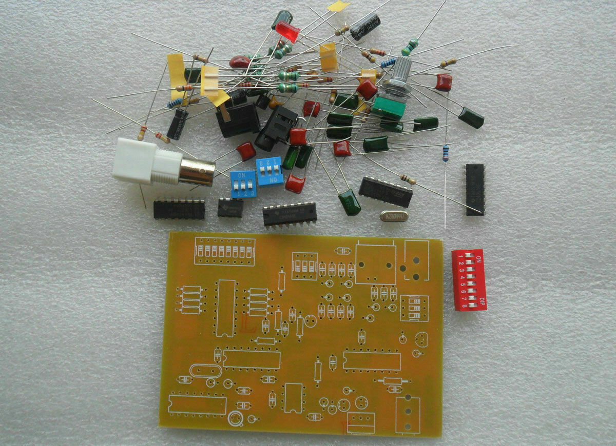
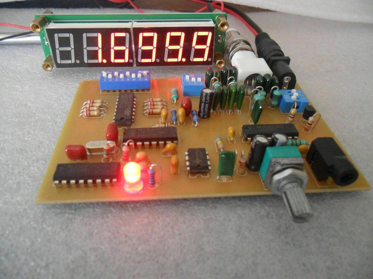
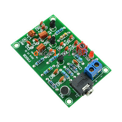
This is a low power AM PLL transmitter for learning.Power supply is 12 V DC.
Frequency adjustment with DIP Switch
Broadcast in the range of 531 to 1602 kHz, each channel spaced 9 KHz
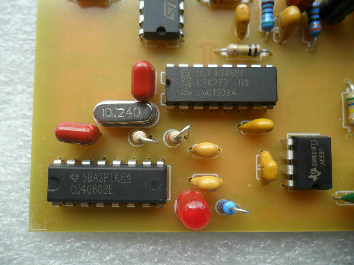
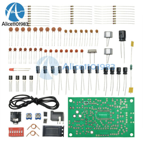
Yes! this kit include 9.216 and 10.240 MHz crystal.
**Modify to 10 KHz step for America
n see below.
Principles of circuit operation. (By
mauric222
)
IC3 CD4060 generates a reference signal for the PLL circuit using a crystal frequency 9.216 MHz. The frequency of the crystal is divided by 1024 using the frequency divider within the IC. The frequency of 9 KHz goes out on pin 14 of IC3.
IC4 HEF4046,is a phase locked loop (PLL) and acts as a phase comparison and VCO. The phase comparison process compares the phase of two signals, the reference signal from IC3 and the signal from IC5. The two signals have the same frequency but different phases. The PLL compares the two signals and generates an error voltage to maintain the proper phase relationship between the two signals. . We will apply this error voltage to control the frequency of the VCO within the broadcst band. but before using it, we need to filter the high frequency signal compnents with an RC low pass filter which is connected to pin 9 of IC4. C24 and R9 define the VCO frequency range within the broadcast band.
IC5 CD40103 acts as a frequency divider (÷ N) IT samples the frequency from the VCO Out (pin 4 of IC4, the phase locked loop.
We can set the divisor by switch SW1. For example, if we need to broadcast at a frequency of 1,008 KHz, we set to divide by 111 . The output frequency of IC5 then becomes equal to 9.08 KHz. This new frequency corrects the phase of the VCO to determine the operating frequency of the PLL which now becomes 1008 KHz.
SW1 switch must be set to a binary code, for example, if we divide by “111” in decimal , this number must be converted to binary. That value is “01101111” IC1 LM358 is an Op-Amp that amplifies the audio signal from low-power to high power to be suitable for use by IC2.IC2 CD4053 acts as a mixer, receiving audio signals to pin 1 and pin 13 mixed with radio frequency signals received on pin 10 and pin 11. The modulated signal is output on pin 14 and pin 15. The signal is strong enough to be used in a room.
We need to provide some amplification to use it outside of a room. Q1 is 2N3904 and acts as RF power amp to amplify radio signal strength to increase the broadcast distance . Before transmitting, the signal must pass through a low pass filter which also provides impedance matching. Since, the frequency range of 531 - 1602 KHz is a wide frequency range we divided the frequency into 3 range. It is necessary to select the correct frequency range with the DIP switch.
An antenna can be used in many ways, but for home use you can use a 3-5 meter long power cord as an antenna and some sort of a ground will also increase the transmit range.
Frequency setting
Adjust the frequency by setting the switch SW1, Like the example in the picture. If we want to send a signal at 1,602 KHz. Set the switch to 10110001.
* Note 1 mean the switch “ON” and 0 mean the switch “OFF”.
Frequency range selector switches.
Both switches are installed in the same direction as in the figure.
Number 1 is “ON” for frequencies 1,200 - 1,600 KHz.
Number 2 is “ON” for frequencies 800 - 1,200 KHz.
Number 3 is “ON” for frequencies of 530 - 800 KHz.
Sample Video
Modify to 10 KHz step for America
n.
Change the crystal from 9.216 MHz to 10.240 MHz , For the 10 KHz step and use this frequency table.
Change the crystal from 9.216 MHz to 10.240 MHz

